Table of Contents
Instructions to read prior to installation
For safety reasons it is important to read the Directions for Use for Mobile Griff before istallation of this equipment. In addition, the legislation in force at the time of purchase must always be considered in connection with the installation and mounting of this equipment.
- The Trolly is a kit that needs to be put together before the unit can be mounted on the Trolly.
- The assembly of the Trolly may only be carried out by trained personal, do not attempt to do it if you have not received training.
- The mounting of the unit onto the Trolly may only be carried out by trained personal, do not attempt to do it if you have not received training.
Transportation of Mobile Griff/XP foamer
For secure transportation of the unit, we recommend always to ensure, that the unit can not slide or tip. The unit might have to be secured with straps.
- Transportation of the unit only in vertical position:
- In case the unit is moved at a temperature of approx or below 0°C (32°F), you must always make sure that the the unit has been fully emptied for water. If this is not the case, you may damage the unit.
Electrical Connection Mobile Griff/XP foamer
Before the unit is connected to the electrical outlet make sure the outlet is connected to a fuse of 16 A.
Make sure the outlet fits the plug on the unit, if not change the plug on the unit.
Do not change the plug your self get a certified electricians to do the plug change.
Make sure that sufficient power supply is available:
- 3 phases 480V/60Hz, and kW that varies depending on number of users from 6kW for 4 users up to 44kW for 32 users
- Since these units are with frequency inverter the ELCB must be of type B, and have sufficient A (Amps) as well.
Water Connection Mobile Griff/XP foamer
Before the unit is connected to the water supply pipe, the supply line should be rinsed carefully in order to remove coarse impurities and metal shavings.
The connection for water must be made at the right side of the unit. (for additional details regarding the requirements to the water supply pipe see drawing 110003704, 110003703).
Minimum internal diameter of the supply pipe must be at least 1/2” external.
The supply pipe must be fitted with a closing valve for water on the inlet (see drawing 110003704, 110003703).
The pressure loss in the supply line must be held as low as possible by:
- avoiding long supply pipes
- mounting low pressure resistance ball valves and
- avoiding fittings with high pressure loss.
When installing the piping, take care to avoid air traps.
All pipe connections to the unit must be screwed connections ensuring simple maintenance and dismantling of the station.
Max. allowed temperature of supply water: 70°C (158F)
Max. allowed pressure of supply water: 40 bar (580 psi)
Water consumption at rinsing mode: 30 l/min (7.9 gpm).
- For an optimum functioning of the injector system, we recommend installing a filter on the inlet to avoid impurities.
Always make sure sufficient water supply is available:
- Boosters and mainstations require a 2 bar (30 psi) dynamic inlet pressure. Not 2 bar (30 psi) against a closed ball valve, but 2 bar (30 psi) when the unit(s) is in operation and using water.
- The water volume available shall correspond to the number of simultaneous users +10%.
Example
A customer wants a system for 6 simultaneous users, and they shall therefore supply minimum;
- 2 bar (30 psi) dynamic inlet pressure
- 6x 8 gpm = 181 l/min (48 gpm) + 10% = 196 l/min (52 gpm)
Air Connection Mobile Griff/XP foamer
The unit have an internal air supply via a compressor. No special actions are necessary before use.
Supply of chemicals Mobile Griff/XP foamer
Unit without User Pack System.
Place the cans with chemical products in the can holder
Check the suction filters for impurities.
Put the suction hoses into the cans below product level and avoid suction of air.
After pre-rinsing, check again that the hoses is sufficiently below product level and avoid suction of air during foam or spray operation.
After use of and when changing product as well as after use of the unit, remove the hoses from the cans and rinse the product inlet lines and injectors with clean water.
Unit with User Pack System
See drawing no 110004594.
Place the specially designed User Pack in the automatic holder.
If changing to a different product when ending the cleaning process, rinse the product inlet line with clean water as follows:
Replace the User Pack containing product by one with clean water; place the foam nozzle and open the spray gun/outlet valve. The product inlet line is now rinsed with clean water before use of another product.
Hose Connection Mobile Griff/XP foamer
The special hose fitted with spray gun/outlet valve is connected to the outlet quick coupling of the unit (layout drawing).
Maximum hose length: 25 m/ 82 ft.
It is recommended only to use Nilfisk FOOD hoses, which have been tested for chemical resistance and general wear and tear.
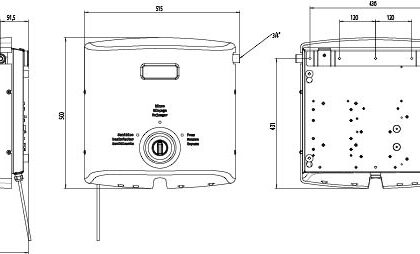
Installation & Mounting drawing Mobile Griff/XP foamer
Installation & Mounting drawing Mobile Griff/XP foamer
Videos

How to mount griff xp foamer on trolley

How to use griff/xp foamer
")