Table of Contents
Instructions to read prior to installation
For safety reasons it is important to read the Directions for Use for Hybrid-P Multi Booster & Hybrid-P Single Booster before istallation of this equipment. In addition, the legislation in force at the time of purchase must always be considered in connection with the installation and mounting of this equipment.
- The unit should be mounted in frost-free rooms only.
- The unit can be mounted on a wall or on a separate frame which may be installed in production areas and anchored to the floor.
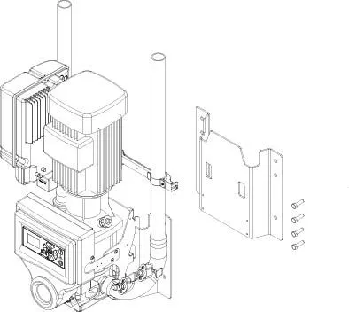
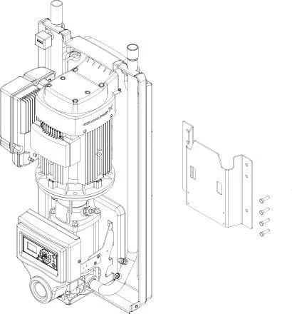
- For mounting on walls, please note the following:
- The wall for mounting should be either a stable brick wall or a wall made of concrete.
- The delivered bracket should be secured to the wall by the enclosed screws and corresponding dowels
- The wall bracket should be mounted on the wall according to the above description and the station is hung on to the bracket.
Transportation of Booster Units
For secure transportation of the unit, we recommend always to ensure, that the unit can not slide or tip. The unit might have to be secured with straps.
Transportation of the unit only in horisontal position: The unit must not be placed on the front where you find the operation panel. Neither can it be placed on top or bottom where connections and outlets are mounted.
In case the unit is moved at a temperature of approx or below 0°C (32°F), you must always make sure that the the unit has been fully emptied for water. If this is not the case, you may damage the unit.
Power supply Booster Units
- Connection instruction is mounted on the cables.
- The phase order is subordinated.
Earth Leakage Circuit Breaker (ELCB).
When using an earth leakage circuit breaker (ELCB) also known as a residual current device (RCD) or a residual current circuit breaker (RCCB) in a system that incorporates a variable speed drive connected to 3 phases, 380 to 528Vac 50/60Hz
– The trip level of the ELCB has to be 300 mA. (30 mA used in house hold will malfunction due to earth leakage)
Service Switch
The unit must always be connected to the main supply through a separate service switch.
NB! Installation must always be in accordence with local legistration.
Water Connection Booster Units
Before the unit is connected to the water supply pipe, the supply line should be rinsed carefully in order to remove coarse impurities and metal shavings.
- The connection for water must be made at the top of the unit. (see layout drawing).
- Minimum internal diameter of the supply pipe must be at least 1 1/4” external (ø36mm internal).
- The unit must be fitted with a closing valve for water on the inlet (see drawing 110003601).
The pressure loss in the supply line must be held as low as possible by:
- Avoiding long supply pipes
- Mounting low pressure resistance ball valves and
- Avoiding fittings with high pressure loss.
When installing the piping, take care to avoid air traps.
All pipe connections to the unit must be screwed connections ensuring simple maintenance and dismantling of the station.
- Max. allowed temperature of supply water: 70°C (158F)
- Max. allowed pressure of supply water: 2-8 bar (29-116 psi)
Filter recommendations: For an optimum functioning we recommend installing a filter on the inlet to avoid impurities.
Min. Filter mesh size 800µ → 1500μ.
Make sure that sufficient water supply is available:
- The boosters and mainstations require a 2 bar (30 psi) dynamic inlet pressure. Not 2 bar (30 psi) against a closed ball valve, but 2 bar (30 psi) when the unit(s) is in operation and using water
- The water volume available shall correspond to the number of simultaneous users +10%.
Example:
A customer wants a system for 6 simultaneous users, and they shall therefore supply minimum:
- 2 bar (30 psi) dynamic inlet pressure
- 6x 8 gpm = 181 l/min (48 gpm) + 10% = 196 l/min (52 gpm)
Air Connection Booster Units
Note: The pump should be bled and filled with water before start.
In order to ensure a problem-free start up of a new system the pipe system must be flushed and bled.
Bleeding the pipe system
- Turn on the water supply to rinse and bleed the entire system. If satellites are installed open the tap furthest away until no air or dirt comes out. Then rinse and bleed the next tap and continue until the tap closest to you has been rinsed and bled.
- Mount satellites, if any
Bleeding the pump
- Loosen the relief plug (A) 1-2 revolutions until water and air begin to flow out.
Never loosen the relief plug while the pump is running as this may damage the packing.
- Tighten the relief plug again
- Start the pump so that all remaining air pockets are forced up to the top of the pump.
- Stop the pump
- Loosen the relief plug 1-2 revolutions again and bleed the system until only water flows out.
- Tighten the relief plug once more
The booster is now ready for operation.
Press “I” on the control panel.
Before Operation
- If the wall the unit is to be mounted on is made of bricks or concrete, the enclosed screws and rawl plugs are usable, otherwise you have to make sure that the carrying capacity of the wall is sufficient.
- The pipeline must be rinsed through before the system is connected.
- It may be necessary to bleed the pipes and the unit again after it has been closed for a longer period of time (holidays, and the like)
- Make sure that sufficient air supply is available (this applies for installations with mainstations and satellites):
- Each unit that has an outlet for cleaning requires an air pressure of min. 87 psi to make foam
- It is important that the compressor has sufficient volume as well so that we ensure enough air to generate nice thick foam. Each outlet requires 5,3 cfm.
Example
A customer wants a system for 6 simultaneous users, and they shall therefore supply min.;
- 87 psi air pressure
- 6x 5,3 cfm = 32 cfm
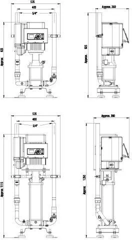
Installation & mounting drawing Booster Units
Booster Wall
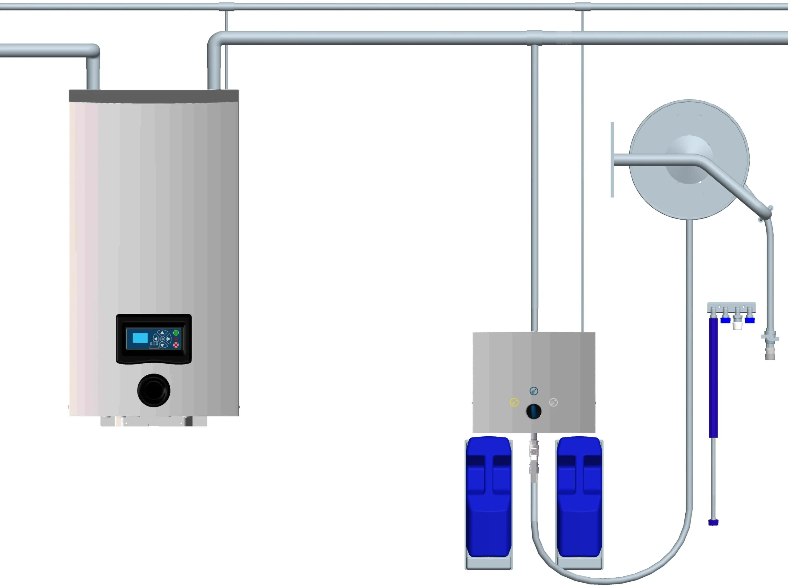
Booster Floor
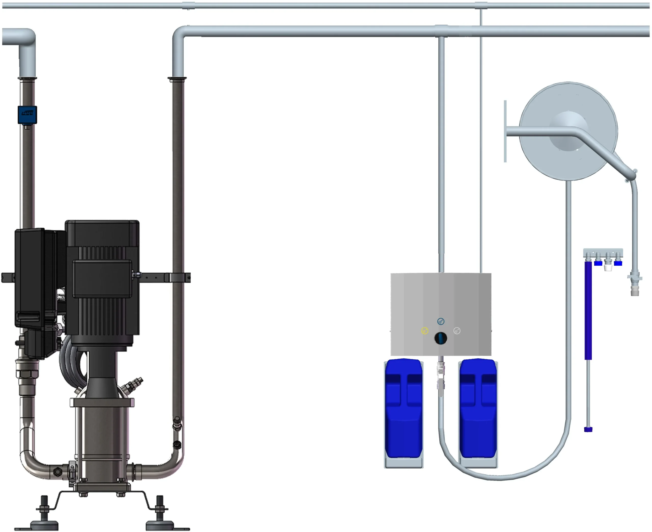
Hybrid-P BW7
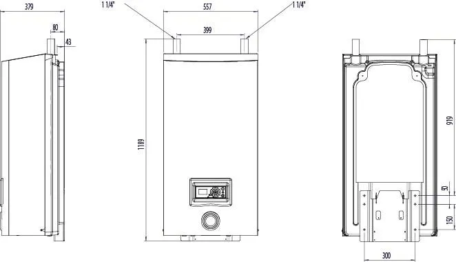
Pegasus-P BW4
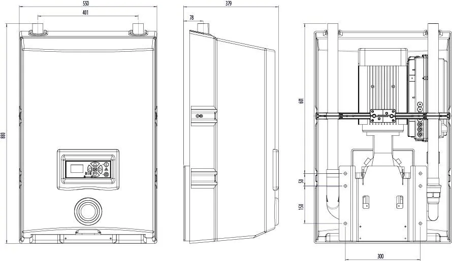
Hybrid-P BF4 & BF8
Pegasus-P BW4
Hybrid BW7
Piping Guideline
To transfer the pressure (energy) from the boosters or mainstations to the satellites without too much pressure loss, it is important to engage with the customers preferred contractor to secure sufficient pipe diameter. The less pressure loss we can have, the more energy we are able to transfer onto the surfaces that are to be cleaned. More mechanical impact on the surfaces = faster and better cleaning. Side effects are a reduction in labor, energy, and water while improving microbiology.
Piping guidelines can be found under each mainstation and booster on our website.