Table of Contents
Instructions to read prior to installation
For safety reasons it is important to read the Directions for Use for Hybrid SU, Hybrid SD,Hybrid Yeti and Hybrid ECO before installation of this equipment. In addition, the legislation in force at the time of purchase must always be considered in connection with the installation and mounting of this equipment.
Directions for Mounting
- The unit should be mounted in frost-free rooms only.
- The unit can be mounted on a wall or on a separate frame which may be installed in production areas and anchored to the floor.
- For mounting on walls, please note the following:
- The wall for mounting should be either a stable brick wall or a wall made of concrete.
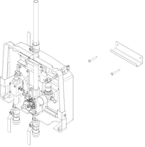
- The delivered bracket should be secured to the wall by the enclosed screws and corresponding dowels
- The wall bracket should be mounted on the wall according to the above description and the station is hung on to the bracket.
- The hose and User Pack holders should be mounted afterwards.
The unit must always be connected to the main supply through a separate service switch.
NB! Installation must always be in accordence with local legistration.
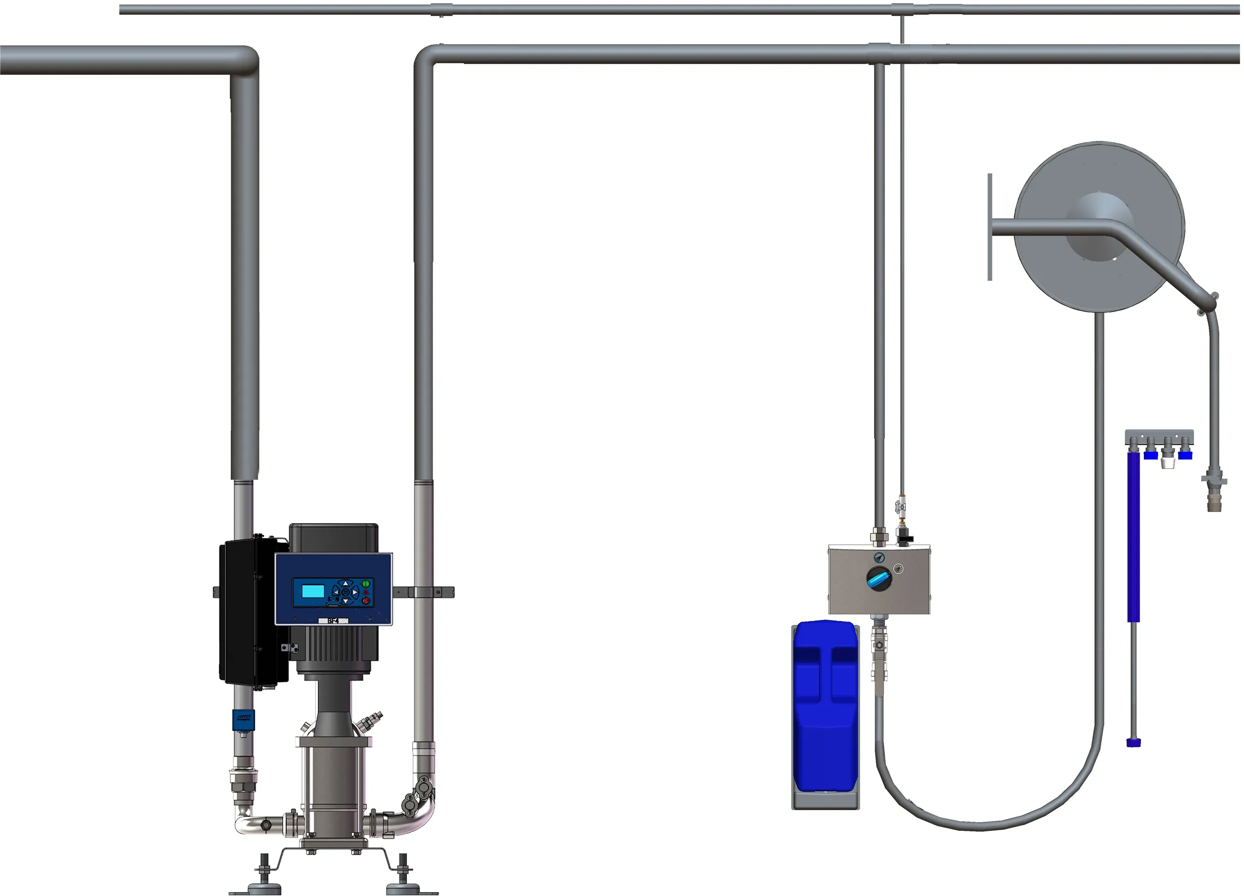
Water connection Hybrid Satellites/Drop stations
Before the unit is connected to the water supply pipe, the supply line should be rinsed carefully in order to remove coarse impurities and metal shavings.
- The connection for water must be made at the top of the unit.
- Minimum internal diameter of the supply pipe must be at least 1/2” external (ø16mm internal).
- The unit must be fitted with a closing valve for water on the inlet.
The pressure loss in the supply line must be held as low as possible by
- Avoiding long supply pipes
- Mounting low pressure resistance ball valves and avoiding fittings with high pressure loss.
When installing the piping, take care to avoid air traps.
- All pipe connections to the unit must be screwed connections ensuring simple maintenance and dismantling of the station.
Max. allowed temperature of supply water: 70°C (158F)
Max. allowed pressure of supply water: 40 bar (580 psi)
Water consumption at rinsing mode: 30 l/min (7.9 gpm)
For an optimum functioning of the injector system, we recommend installing a filter on the inlet to avoid impurities.
Always make sure sufficient water supply is available:
- The boosters and mainstations require a 2 bar (30 psi ) dynamic inlet pressure. Not 2 bar (30 psi) against a closed ball valve, but 2 bar (30 psi) when the unit(s) is in operation and using water.
- The water volume available shall correspond to the number of simultaneous users +10%.
Example
A customer wants a system for 6 simultaneous users, and they shall therefore supply minimum;
- 2 bar (30 psi) dynamic inlet pressure
- 6x 8 gpm = 181 l/min (48 gpm) + 10% = 196 (52 gpm)
Air connection Hybrid Satellites/Drop stations
Before the unit is connected to the air supply, the pipe system must be carefully rinsed in order to remove coarse impurities.
The unit requires an air supply boosting
- an inlet pressure of minimum 6 bar
- a minimum capacity of 200 l/min.
The air supply pipe is connected directly with a quick fitting for easy dismantling. In all units an inlet valve with 1/4” thread is fitted.
Make sure that sufficient air supply is available (this applies for installations with mainstations and satellites):
- Each unit that has an outlet for cleaning requires an air pressure of min. 87 psi to make foam
- It is important that the compressor has sufficient volume as well so that we ensure enough air to generate nice thick foam. Each outlet requires 5,3 cfm.
Example
A customer wants a system for 6 simultaneous users, and they shall therefore supply min.;
- 87 psi air pressure
- 6x 5,3 cfm = 32 cfm
Chemical supply Mainstation MU/MD

Satellite with User Pack System
- Place the specially designed User Pack in the automatic holder.
- If changing to a different product when ending the cleaning process, rinse the product inlet line with clean water as follows:
- Replace the User Pack containing product by one with clean water; place the foam nozzle and open the spray gun/outlet valve. The product inlet line is now rinsed with clean water before use of another product.
Supply of Detergent
Satellite without User Pack System.
- Place the can with detergent in the can holder
- Check the suction filter for impurities.
- Put the suction hose into the can below product level and avoid suction of air.
- After pre-rinsing, check again that the hose is sufficiently below product level and avoid suction of air during foam or spray operation.
- After use of and when changing product as well as after use of the unit, remove the hose from the can and rinse the product inlet line and injector with clean water.
Hose connection Hybrid Satellites/Drop stations
The special hose fitted with spray gun/outlet valve is connected to the outlet quick coupling of the unit.
- Maximum hose length: 30 m.
- It is recommended only to use Nilfisk-FOOD hoses, which have been tested for resistance.
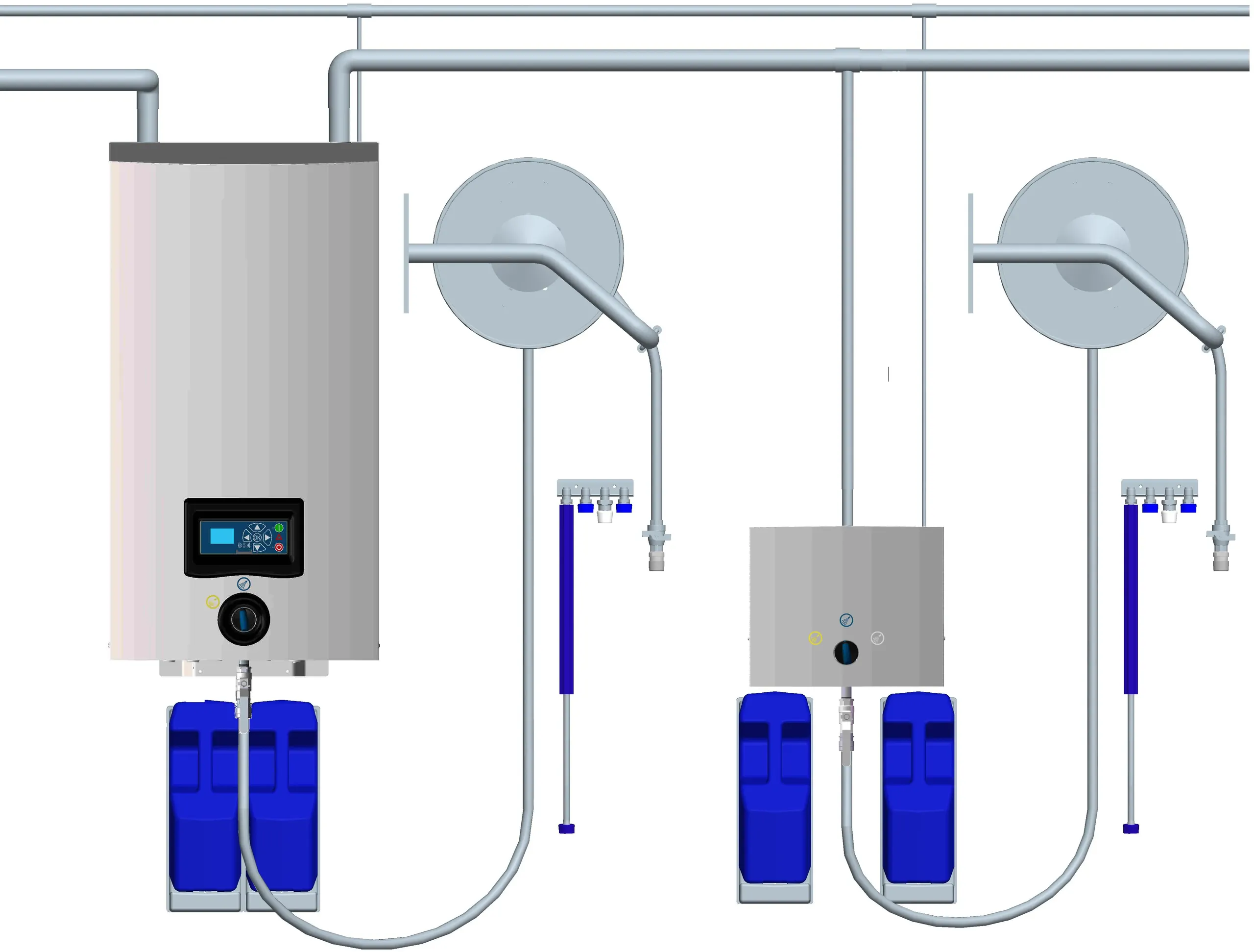
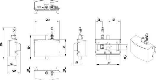
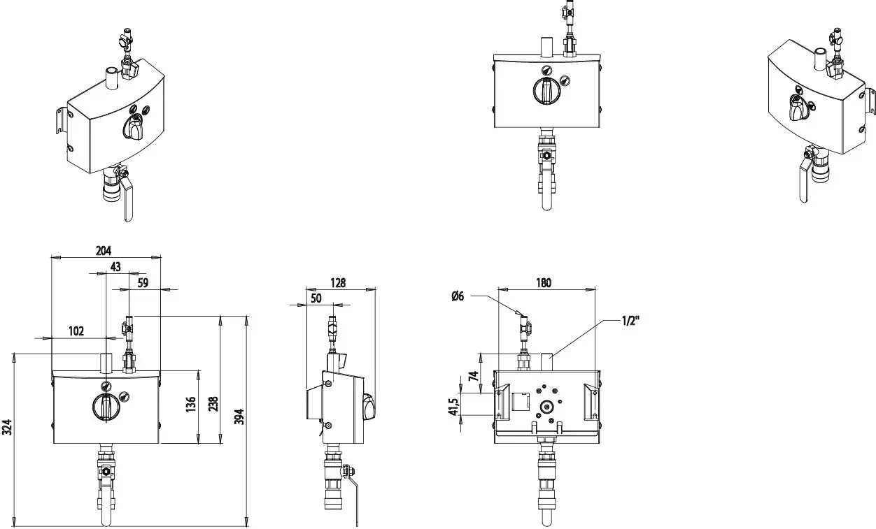
Installation & mounting drawing Hybrid MU/MD
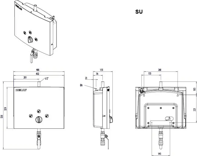
Hybrid SU
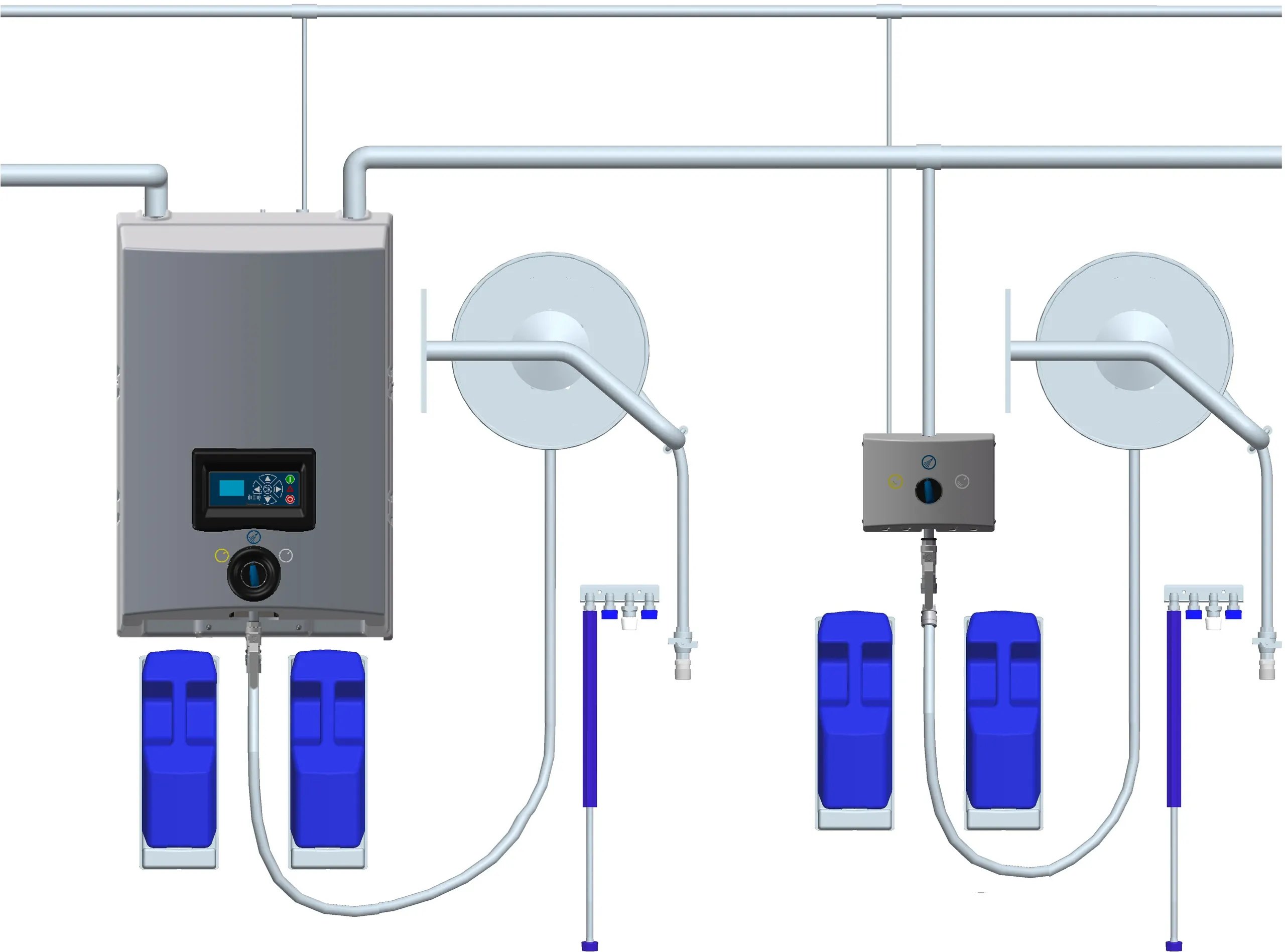
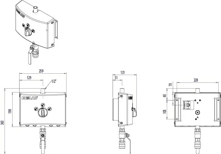
Hybrid SD
Hybrid Yeti

Hybrid ECO
Videos
Unboxing and mounting Satellites/Dropstation

From 1 Foam product to 2 Foam products
– How to change the positioning plate
")